Monday, April 25, 2011

LED Lights

When I took off the bumper, the flasher plastic clips/connectors broke off.  I looked everywhere to find a replacement and even toyed with the idea of fitting in standard wiring harness but since the flasher casing was metal that wasn't going to work. OK, it was a good excuse to replace with LED flashers.  In addition, WA State law requires cars to have side lights as well.  So I bought some off of EBay and got a great deal.  The only thing I noticed was that in some cases the white wire was the ground - not the black.  I would encourage everyone to test your LEDs right out of the box so you have no doubt.

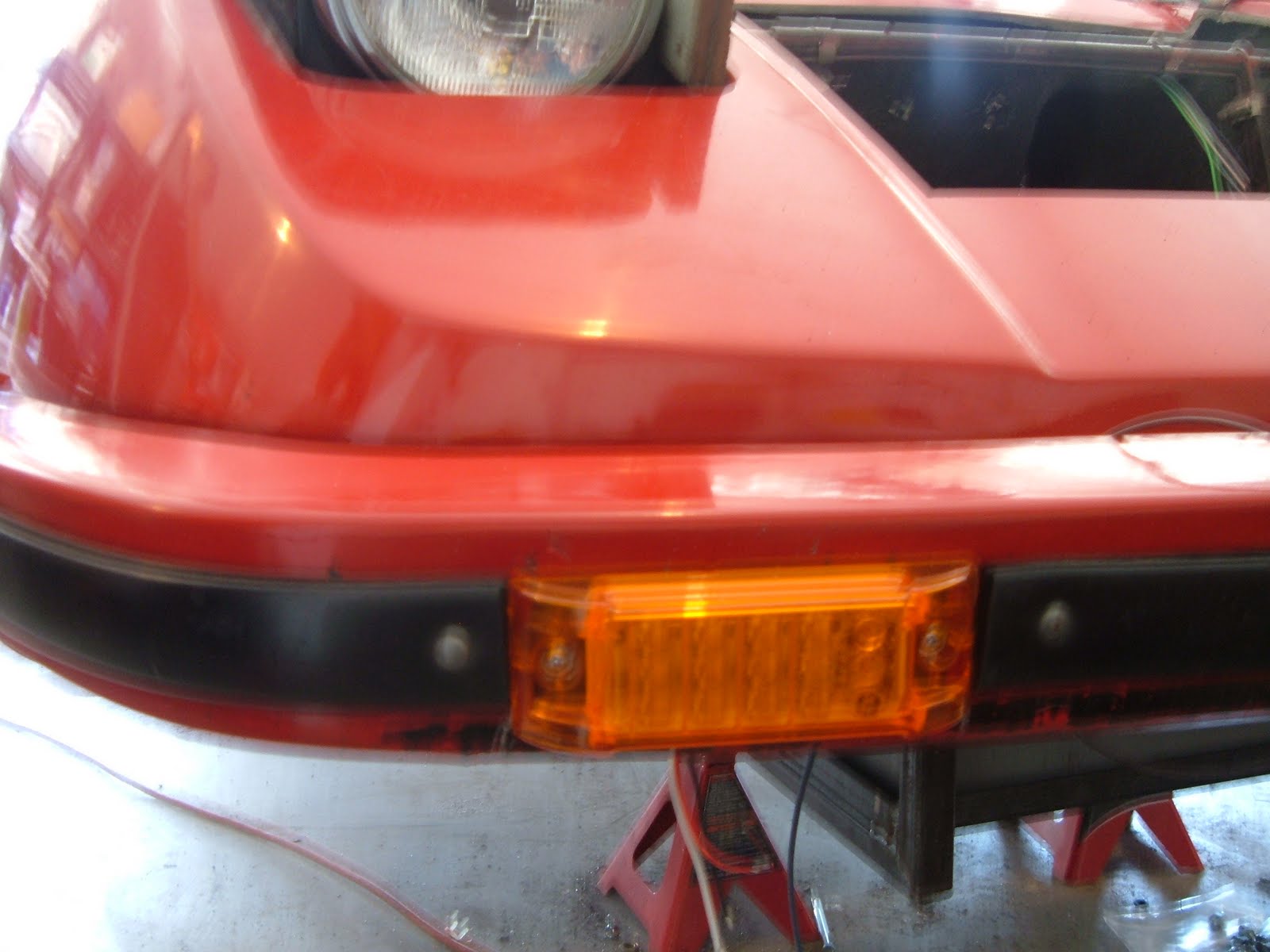
The original flashers were mounted in the bumper and were approx 5.25 X 1.75 inches.  The best I could find was 2X6 flush mount.  I took the old ones out and then traced the pattern on a 1/2 inch piece of plywood. This way I could use the original screws to hold the wood in the bumper then drill my holes in the wood for the flasher to attach to it. I also had to cut a little off the black rubber on the sides to make the full 6 inch width work.

The other thing I caught was the flasher requires two power wires going to it.  I found a great wiring diagram/PDF at EZ2Wire which showed how that was supposed to happen.  The site I got the EZ Wire harness from didn't have anything like this.

http://www.goindesign.com/w4r/EZ2Wire-Manual.pdf

This is very similar to what I am using.
Here's the side lights, also flush mount.  The thought of having to cut an exact fit hole in the fiberglass for a side light a flasher is a level of expertise I'm not ready for.
  This was mounted six inches from the fender, which is approx halfway between the fender and bumper.

I also added some electrical panel buss bars so all the grounds will be in one place.  This makes finding any ground faults easy.  They say that is the number problem in electrical connections. These buss bars have a 10 ga wire that connects to the chasis.  There will be five total, 2 in the front, 2 in the back and one long one in the driver's side, by the fuse panel.

Next time we'll see the rear side lights, back up, 3rd brake light, etc....

Master Cylinder Replacement

So how tough can this be?  2 bolts behind the pedals.  Both of these bolts are 13 mm, I think.  It's not the bolts themselves that are so tough - it's where they are placed.  I'm 6 ft tall, trying to get in there to remove them is like sticking 10 lbs of mud in a 5 lb sack.  It's tight.  If you are claustrophobic, get someone else to do this!
The bolt on the right side is best taken out with a long extension on the ratchet wrench.  Also, there's some spacers that are between the two body walls that the bolts go through. This ensures the two walls don't get pushed in toward each other in case you over-tighten the bolts.  It's easy to lose these, you can stick your fingers inside the hole and find them if they fall off the bolts.  The best tip I found from the shade tree mechanic website: if the bolts are out and the cylinder is still stuck, use a rubber mallet and beat the crap out of it until it comes loose.  Don't make the mistake of thinking you have to completely take off the piston device from the pedal.
The picture is fuzzy but I think you get the point, this one was rusty and in sad shape.  For $35 you get a brand new one.

This has the two brake light switches attached as well as a new reservoir tank that attaches to the cylinder.  If I don't like this I can use the original valves that come with the cylinder and hook it up with some hoses.
To put the new one in, you'll need a helping hand.  My wife held it in place while I tightened the bolts.

Sunday, April 10, 2011

EZ Wiring Part I

Time to get serious about rewiring the whole car.  Many rebuilders have gone insane trying this.  Some have cried "Uncle" and called some one else in to do this.  I have to say, I have spent many hours looking at the 1967 VW schematic and then the EZ wiring diagram.  What confounds the issue is what wires hooks up to the steering wheel.  They give you a standard GM diagram and connections.  The 1967 VW has a black box thingee that ran a lot of the lighting.  Weird.  Then the final consideration is what do I NOT need because I'm driving electric.

You'll need a pulling device like the one above.  I also found using velcro ties a great luxury.  The first step is to have a plan. What goes where?  The EZ Wiring is laid out in four sections, the front, the back, the dash, and the steering wheel.  Step two is laying it out next to the car.  If you have a crowed garage like I do, then you'll drag it into the dining room and move the wires around as need be.  The kit assumes that the engine is in the front, not the rear.  So some wires had to be rerouted.  That's where the velcro ties work very well.  They give you plenty of wire ties but I didn't want to have to keep cutting them and putting in new ones.

Here are some of the wires waiting to be pulled.  The route to the back was next to impossible.  If you had the body off the car and the whole thing turned upside down you could do that.  I notices that there's a lip large enough along the 3 inch lift to run the wires along there and then use the same hole I cut for the the high voltage wires earlier in the backseat area.
The front wasn't too bad.  The puller was a great tool to use.
And the fuse box went right where the old one was.

Pretty Dash

OK, I said that I needed to get her running then make it pretty.  Well, I got a wild hair the other day and started the think about how I would replace the area in the dash that holds the gauges, mine was broken at the bottom.  I had some plexiglass laying around and thought wouldn't it be cool to use this.  Then instead of a clear view, let's scratch it up with some fine sand paper and have a frosted look.
This stuff like butter if you use a general purpose blade on a angle grinder.
I plan on covering all the holes in the area just to the right and left of the steering wheel with the same.  Now, if I added some LEDs behind them....just thinking.

Electric Heat

Previously on LOST Defroster, our hero discovered there was none.  This is because I am working on a standard Bradley GT II and NOT the GTE.  Evidently they had a 12V ceramic defroster in the front firewall area.  This defroster from what i have read was insufficient.  An ICE version of the Bradley GT, would get it's heat from the motor in the back.  There were two little handles next to the emergency brake that you used to open the duct and heat would flow from the back to the front. Right....that too was sufficient.  Many Bradley and VW owners have froze there tails off.

EVs must rely on electric heat in one form or another.  Some use a heating element and use the existing AC/heater unit.  (from what I have read, this is a waste of money)  Others use a heavy duty ceramic element heater. The argument here is that it burns too much energy from your pack.  Since I built my pack too large for my daily commute, I think this will work just fine.


So once again I rely in part on some parts from the previous EV I used to own - the converted Pulsar.  That owner had a 120V  heater already rigged up but said it never did work.  As I was taking apart and reverse engineering the magic box, I saw he was using a 12V relay for a 120V heater.  I'm thinking that was his problem.  I have a 200V 50 amp relay that will power the heater elements.  A standard 12V fan switch will power the fans.  This switch has a low and high setting.
Here's the plan: put two heating elements in the rear, then place some powerful fans in front of them to suck the heat.  These fans are rated 220 CFM!!!  Most fans are 120.  The biggest argument is the single fan that the Bradley used was always too weak.  You need to get some fresh air in the cabin.  With two fans that blow that much air, I'm thinking I'll avoid that argument. One vent will go to the defroster ducts and the other will go to the passenger vents in the dash.  The pict above was the rough draft so to speak.

I measured carefully and found that the fan needed to go up one inch from the floor of the box to center on the vents. The box couldn't be wider than 18 3/4 inches.  And 8 inches tall seem to be too tall. You also can't be deeper than 8 inches.
Here's the next to final.  I have some heat insulation coming that will help keep the wood from burning and hopefully quiet the fan noise.  I will most likely continue and box the whole unit in so the rain from the vents above won't damage the unit.
I cut some holes in the back to draw the air in.  I might cut holes in the fiberglass on the other side as well.  The draw from the top of the fiberglass box can be inefficient.

The problem I see already is the box hits the wiper relay.  So, I'll have to see if I can't get it to either wiggle in or remove the wiper motor temporarily.

Monday, April 4, 2011

Installing the Front Battery Box

The last time I talked about this I showed how it was made, both the box and support structure but I didn't get around to actually installing the thing until I got my main brackets back from the welder.  Those brackets need to be able to hold over 160 lbs of batteries.
I hate to cut fiberglass but in this case I have to.  Besides, in the original plans with the GTE subframe, a Bradley front end must be cut!  Very similiar to what I'm doing here.

The cut has been made...let's move on!  I used the box underneath to steady the frame while I tried to get the first muffler clamp on.  Another trick was to use a cable wrap to hold the back end up as well.
Oops. The box didn't quite clear the steering box.  A quick slice from my sabre saw and we're back in business.  At one point I thought maybe I was going to have to install the clamps with the box in place.
Here's a 160 lbs of batteries and it's holding just fine.  I jumped up and down on the front bumper and there was no sliding between the main bracket and the chassis.

3 Inch Lift Update to front bracket

After getting advice from a guy on Bradley GT.com I decided to get rid of the brackets that I installed to marry the front end to the chassis.  If you remember adding that 3 inch lift moved everything up three inches and so the bracket didn't marry to the chassis like it had before, with an indentation to stop the chassis from sliding up and down. 
So I got my welder to add a 3 inch channel to the original so it would now be extended by 3 inches.
Here I just got finished grinding in a new circle shape so the bracket will marry to the chassis pipe.
Did the same on the bracket to the smaller bracket on the opposite side.

Now, it marries up and the possibility of sliding is much less.  Why go through this?  I'm adding 160 lbs of batteries to the front that will hang off the pipe that connects the front bumper.

EV Wiring Part II

I got busy this weekend and worked on getting the quick disconnects installed in the middle console.
This what the console looks like upside down.  To install these BRBs or Big Red Buttons you have to take off the big red buttons.  Hmmm..... they don't come off with a screw driver, they don't pop off, lookie there - there's a hole in the metal stem that goes up the middle.  Stick a nail in there and now the big red buttons actually screw off!  Drill some holes then in it goes.
Now the cables go from the back to the front and back to the rear.  Now I can break the pack up into three sections and only have the possibility of getting shocked by 60 volts instead of 156 volts!  I also cut a 2 inch hole in the firewall for the cables to go through,  I used 2 inch PVC pipe connectors to make it solid.  Eventually I'll fill the holes with expanding foam to seal it off from the cold air.

I still need to add some more wires - BMS, Blue window, power, etc....